Pneumatic Muscle-Driven Lower-Limb Rehabilitation Exoskeleton: An Engineering Teardown of a Typical Structural Design Case
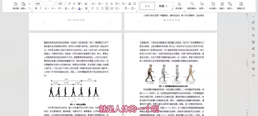
As the boundary between consumer-grade exoskeletons and rehabilitation exoskeletons becomes increasingly blurred, reverse-engineering product thinking from structural design cases often yields greater information density than watching finished-product launch events. This episode showcases the complete design workflow of a lower-limb rehabilitation exoskeleton robot—from 2D drawings and 3D models to a full set of design documentation (KT package). It lays out the question of "how to move an exoskeleton from concept to assembly-ready" with considerable clarity. A point worth stating upfront: this design inherently belongs to the rehabilitation exoskeleton (medical/rehabilitation-grade) category, rather than a consumer-grade exoskeleton aimed at hiking or trekking assist. Nonetheless, the joint layout, flexible actuation, and degree-of-freedom distribution approach it employs offer valuable reference for understanding the entire exoskeleton field.

1. Positioning: What Problems Does a Rehabilitation-Grade Lower-Limb Exoskeleton Solve
The video opens by stating the design objective—to assist patients with lower-limb injuries or walking impairments, providing assistive force that exercises the joints, preventing the joint stiffness and muscle atrophy caused by prolonged inactivity. This stands in stark contrast to consumer-grade exoskeletons like Hypershell and Dnsys, which target healthy users with hiking/trekking assist: the former addresses "whether you can walk at all," while the latter addresses "how to walk with less effort."
Design objective (mentioned in the video): assist patients with lower-limb injuries or walking impairments, providing assistive force and exercising the joints to break the vicious cycle of prolonged inactivity.

From a structural standpoint, the so-called "exoskeleton"—with the assistive mechanism arranged along the outer side of the legs, leaving the space between the legs open for walking assist—is virtually an industry consensus. Whether it's the industrial/rehabilitation product lines from Chengtian and Aoshark, or the lumbar/back assist products from Yuanye and Kenqing, all follow this "external-mounted" layout.


II. Full Assembly: Foot on the Inner Side, Pelvis-Centered Protection
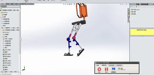
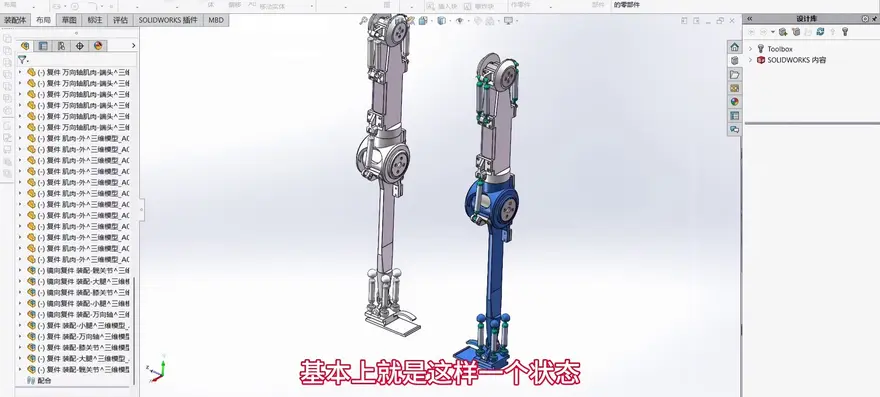
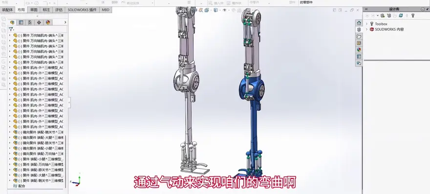
The assembly model shown in the video presents a clear three-segment structure: the foot is positioned on the inner side, covering upward in sequence the three major rehabilitation joints — ankle, knee, and hip — with a protection device set at the pelvis. This layout balances ergonomic fit with mechanism interference avoidance.

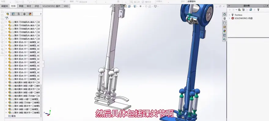
The rehabilitation needs of the three joints are not simply additive: the ankle handles dorsiflexion/plantarflexion, the knee handles flexion/extension, and the hip involves multiple degrees of freedom — flexion, extension, abduction, and adduction. The model in the video covers all three major joints, indicating this is a complete lower-limb chain rather than a single-joint trainer.

Joint coverage (mentioned in the video): three-joint rehabilitation for the ankle, knee, and hip, with a protection device set at the pelvic segment.

The presence of the pelvic protection device is especially critical — it serves as the "interface" between the entire mechanism and the human body, required to both transmit joint torque and prevent direct compression of rigid structures against the human pelvis. This is one of the pain points that distinguishes a rehabilitation exoskeleton from an industrial exoskeleton.

3. Telescopic Rods: Flexible Movement via Four Rods
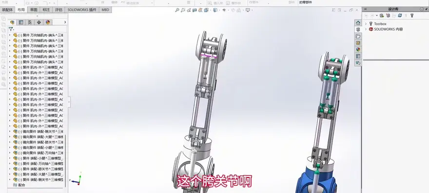
Between the pelvis and the lower-limb mechanism, the designers adopted four telescopic rods to enable flexible movement. This is an engineering choice worth dissecting: compared with rigid linkages, telescopic rods can provide axial length compensation, accommodating pelvic floating and lateral sway during the human gait, thereby reducing the risk of mechanism "jamming."

The symmetric arrangement of the four rods essentially constructs a redundant parallel-series hybrid structure—ensuring symmetric assist on both left and right sides while allowing relative displacement on a single side. This approach is a reasonable trade-off in rehabilitation scenarios where self-balancing requirements are not stringent.

Flexible movement solution (mentioned in the video): adopts four telescopic rods to enable the mechanism to flexibly follow the human body.
IV. Pneumatic Muscle: The Cylinder-Shaped Soft Drive Core
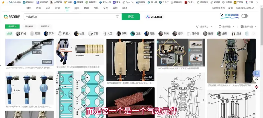
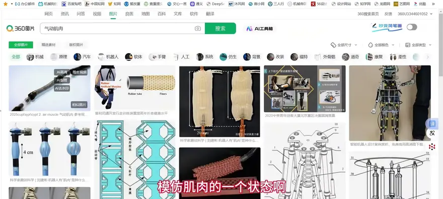
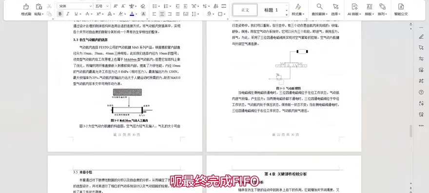
The power source for the entire design is the pneumatic muscle — the most worthwhile technical point to unpack in the video. The designer explicitly clarifies: it is not real muscle, but a cylinder-like pneumatic component. Its shape resembles a cylinder, yet its working principle softly mimics muscle contraction and relaxation, using pneumatics to drive joint bending and flexible rotation.
The advantages of the pneumatic muscle (the typical form of the McKibben-type pneumatic artificial muscle) are: light weight, high compliance, and a large force-to-weight ratio, plus an inherent "softness" — even if the mechanism loses control, it will not inflict a hard impact on the human body the way a rigid servo motor would. This is decisive for safety in rehabilitation exoskeleton scenarios.
But the trade-off is equally clear: pneumatic drive suffers from low control precision, large response latency, and the need for an air source and air circuit, making the overall system volume and weight hard to compress — this is the fundamental reason it cannot move toward consumer-grade exoskeletons. Consumer-grade products (Hypershell, Dnsys, etc.) almost uniformly opt for brushless motor + reducer solutions precisely to sidestep the portability shortcomings of pneumatics.
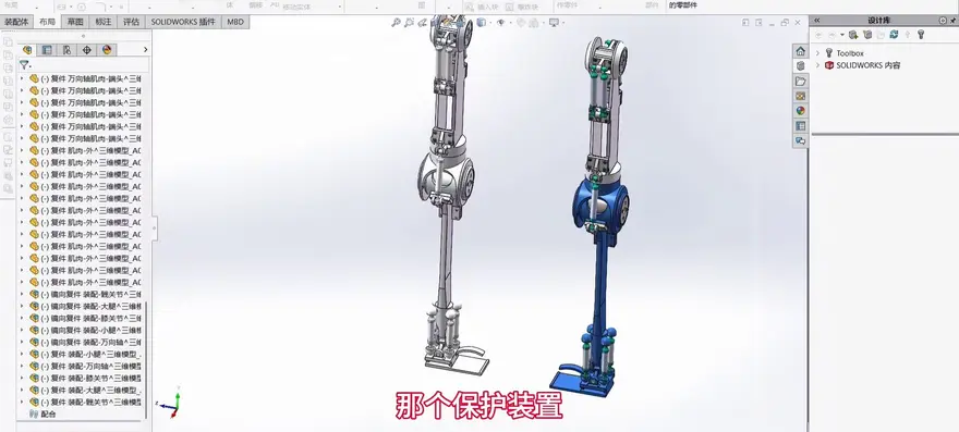
Pneumatic muscle (mentioned in the video): a cylinder-like pneumatic component that softly mimics muscle, using pneumatics to drive joint bending and flexible rotation; not real muscle.
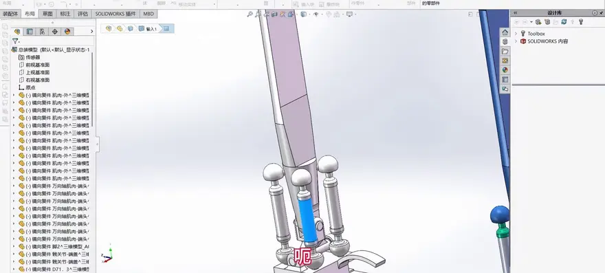
The video notes that this design uses four pneumatic muscles, and frankly calls it "relatively complex" — meaning each joint or each motion direction corresponds to one drive unit, making air-circuit distribution and synchronization control the key challenges for the downstream simulation and control layer.
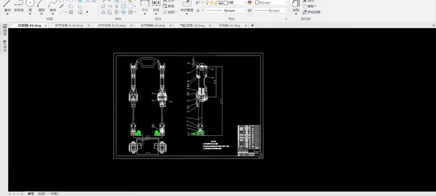
5. The Methodology Chain of the Design Thesis
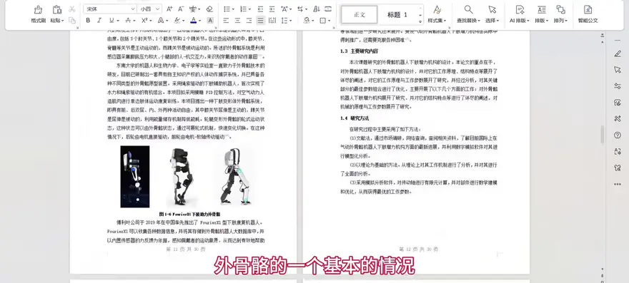
The video breaks down the thesis structure of this design into five clear chapters, which also constitutes a standard methodology for rehabilitation mechanical design:
- Background chapter: introduces the basics of the lower-limb exoskeleton with rich illustrations;
- Ergonomics analysis chapter: based on the basic motion requirements of the human lower limb, completes the overall scheme design of the assistive mechanism;
- Structural design chapter: degree-of-freedom allocation, power source (pneumatic muscle) selection, and pneumatic system design;
- Component design chapter: bearing calculation, verification, and key connection modeling;
- 3D modeling chapter: the final 3D assembly deliverable.
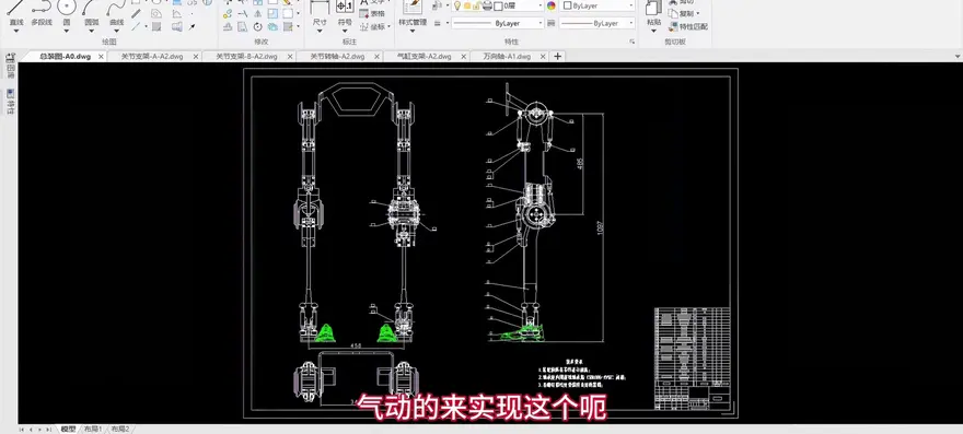
Methodology (mentioned in the video): background → ergonomics analysis → overall scheme → structural design (degrees of freedom, power source, pneumatic system) → component calculation and verification → 3D modeling.
Among these, "degree-of-freedom calculation" is the linchpin of rehabilitation exoskeleton design — too few degrees of freedom and the mechanism cannot conform to the natural gait; too many and both control complexity and weight spiral out of control. The video emphasizes "completing the degree-of-freedom calculation," indicating that this scheme made an explicit trade-off in degrees of freedom rather than relying on guesswork.


VI. Components and Verification: Engineering Details of Bearings and Key Connections
Chapter 4's component design focuses on bearing selection and computational verification, key connection modeling — core textbook-level content in mechanical design, but with special significance in the exoskeleton context: a bearing's load capacity directly determines the upper limit of joint torque transmission, while key connections govern the reliability between pneumatic muscle output and the joint axis.

The video notes that the fit is currently "fixed," meaning this represents a static assembly state rather than a dynamic one — in other words, the current model validates "fits and assembles correctly," not "moves smoothly and stably."

Current state (mentioned in the video): the fit is fixed, and the model cannot yet move; if additional workload is needed, overall motion simulation can be supplemented.

VII. From Static Modeling to Motion Simulation: The Last Mile Remains
The designer candidly noted: the current model "uses four pneumatic muscles, which is relatively complex," and motion simulation "can be skipped since the overall workload is already sufficient." This statement actually pinpoints the real threshold of rehabilitation exoskeleton R&D — static structural design accounts for only 30%-40% of the entire R&D cycle, while the remaining 60% goes to control, simulation, and human-factors experiments.
The coordinated control of four pneumatic muscles involves gas-circuit distribution, pressure-to-displacement mapping, and joint phase synchronization — an order of magnitude more complex than the position control of a single brushless motor. This also explains why consumer-grade exoskeleton manufacturers generally avoid the pneumatic route: controllability is far harder to compromise on than compliance.

If overall simulation is to be added later, the core problems to solve include: gait trajectory planning, the inflation/deflation timing of each pneumatic muscle, pelvic floatation compensation, and most critically — the fall protection strategy. Rehabilitation patients are themselves a high fall-risk population, so this step cannot be omitted.
8. Case Value: Teaching Template and Industry Mirror
Taken together, the greatest value of this lower-limb rehabilitation exoskeleton design case lies not in "building a sellable product," but in fully reproducing the engineering chain of an exoskeleton, from requirements through to 3D assembly. For learners, it serves as a standard textbook covering structural design, degree-of-freedom allocation, and pneumatic system selection; for industry observers, it inversely validates the rationale of the pneumatic route within the rehabilitation field — and its limitations in the consumer space.
Cross-comparison: Chengtian and Aosha lean toward a high-torque route built on brushless motors and rigid joints for industrial handling scenarios; Yuanye and Kenqing adopt lighter elastic-plus-motor hybrid solutions for lumbar / back assist; Haier and Hypershell, meanwhile, bet on consumer-grade hip assist. The pneumatic muscle route, by contrast, still largely remains confined to laboratories and teaching scenarios, some distance away from mass production.
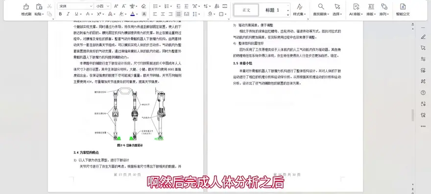
Case positioning (mentioned in the video): A typical rehabilitation mechanical design case, complete with a full set of 2D drawings, 3D models, and design papers — suitable as a structural design teaching template.


Top Community Comments
@Reader (1 like): Asking for the source files
This comment reflects the strong demand for fully editable design assets among exoskeleton enthusiasts and mechanical engineering students — they don't want render images, they want STEP/source files they can actually take apart and study. It also indirectly highlights how scarce such design case studies remain.
@Reader (0 likes): Asking for the files
As above, the repeated appearance of "asking for the files" shows that the audience has reached a consensus in demanding design materials. There is a structural gap between the nature of the video itself (visible but not obtainable) and audience expectations.
@Reader (0 likes): Triple action, asking for the files
"Triple action, asking for the files" is a classic resource-bartering etiquette online — exchanging likes, coins, and favorites for source files. This reflects how such content spreads within the niche mechanical-design community: content as a resource hook, where the uploader trades design case studies for traffic, and the audience trades the triple action for assets.
One-Sentence Summary
This is a rehabilitation-grade lower-limb exoskeleton teaching design case centered on pneumatic muscle actuation, a four-stage telescopic rod structure, and three-joint (ankle/knee/hip) coverage. The engineering pipeline is complete but stops at static modeling; it suits mechanical engineering learners and exoskeleton structure design researchers, and has no direct relationship to consumer-grade exoskeleton (hiking / trekking assist) product positioning — though its degree-of-freedom allocation and compliant drive approach are worth referencing for the industry side.
About this article: part of Chinese-Made Exoskeleton Review Archive — an independent, regularly updated English archive of reviews of consumer exoskeletons made in China, edited from publicly available video transcripts. Not an official manufacturer page.
For inquiries and purchasing, contact lonlonago@foxmail.com. More in Rehab & Mobility · All articles.